Workers
See how the complete machine fits together, what each trade touches and how to describe genuine BWR experience.


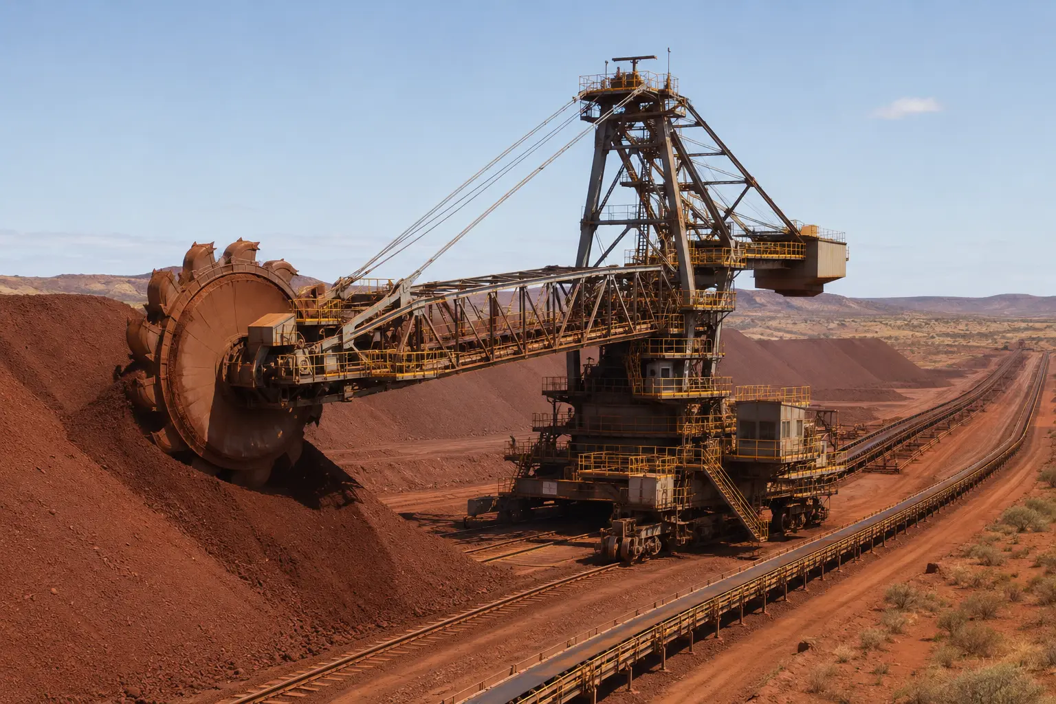
Machine of the Month · September 2026
The stockyard machine that turns a planned pile into a controlled stream of ore. Follow the material path, major systems, controls, shutdown work and supplier questions.
Original conceptual editorial visual · The FIFO Hub · AI-assisted · not an OEM drawing
Capacity, boom and rail-gauge ranges are published for TAKRAF's product family; they are context only, not specifications for every machine.
What the machine does
A bucket wheel reclaimer continuously removes bulk material from a stockpile and transfers it to the next conveyor. On a longitudinal iron ore stockyard, the machine usually travels on parallel rails, slews across the pile face and luffs to work different elevations.
It is not an isolated machine. Reclaim performance depends on the stockpile's shape and material condition, the nominated product, available yard or wharf conveyors, transfer chutes, protection systems and the downstream train-loadout, processing or shiploading plan.
Reclaim rate is not “wheel speed”. It is the result of cut geometry, slew speed, bucket fill, material behaviour and the capacity available downstream.
One asset, four lenses
See how the complete machine fits together, what each trade touches and how to describe genuine BWR experience.
Translate a shutdown scope into access, lifting, isolation, inspection, repair, QA and commissioning requirements.
Match a component to the machine tag, duty, material, drawing, wear history and acceptance criteria before quoting.
Connect stockyard throughput with asset condition, critical spares, obsolescence, controls and outage strategy.
Material path
The precise chute and conveyor arrangement varies. Trace the actual machine from approved drawings before planning work.
The nominated product and reclaim face define the material presented to the wheel.
Rotating buckets cut, fill and lift material from the face.
Material leaves the rising buckets through the wheel discharge arrangement.
The belt carries the stream back towards the machine centre.
A chute loads the yard conveyor for the next stockyard or outloading stage.
Coordinated movements
Buckets cut into the pile face, lift material and discharge it towards the boom conveyor.
The superstructure rotates so the boom sweeps the wheel laterally across the working face.
The boom raises or lowers to reach different elevations and control the reclaim bench.
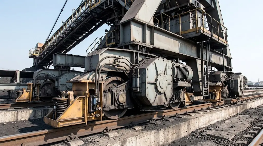
The complete machine moves on bogies along the stockyard rails to reach the nominated pile section.
Machine anatomy
The bucket wheel, boom, slew platform, portal and bogies form one structural and mechanical system. A defect in one area can appear as a symptom somewhere else.
Buckets cut and lift material; the hub, shaft, bearings and drive carry the cutting load.
Receives material from the wheel discharge and carries it back towards the machine centre.
Raises or lowers the boom to work successive elevations of the stockpile face.
Balances the working boom through the counterweight boom, pylon and support system.
Rotates the superstructure so the wheel sweeps laterally across the stockpile face.
Hands reclaimed material from the boom conveyor to the yard conveyor below.
Move the complete machine along its surveyed stockyard rails.
Cable management, drives, PLC, instruments, communications, lubrication and water support the machine.
Component-to-condition map
| Assembly | Function | Condition focus |
|---|---|---|
| Bucket wheel, buckets and teeth | Cut and collect material from the stockpile face. | Lips, teeth, liners, bucket structure, buildup, cracking and uneven wear. |
| Wheel drive, shaft and bearings | Transmit torque and carry the wheel under variable cutting load. | Torque or current trend, vibration, temperature, lubrication, seals, coupling and gearbox condition. |
| Boom conveyor | Move reclaimed material from the wheel discharge to the machine centre. | Tracking, belt and splice condition, idlers, pulleys, cleaners, skirts, take-up and drive health. |
| Boom and support structure | Carry the wheel, conveyor and dynamic loads through the machine. | Fatigue-prone details, deformation, corrosion, pins, bushes, welds and bolted connections. |
| Slew bearing and drives | Rotate the upper machine and transfer axial, radial and overturning loads. | Bolt preload evidence, grease and seals, raceway condition, backlash, drive pinions and abnormal vibration. |
| Luffing system | Change boom elevation using winches, ropes or hydraulic cylinders. | Ropes, sheaves, drums, brakes, pins, cylinders, hoses, seals, rod condition and position feedback. |
| Counterweight and pylon system | Balance the cantilevered working boom and stabilise the load path. | Counterweight security, support ropes or rods, pins, bushes, corrosion and structural connections. |
| Central transfer and chutes | Transfer material from the boom conveyor to the yard conveyor. | Liners, buildup, impact zones, blocked-chute protection, skirting, dust and spillage. |
| Long-travel bogies and rail | Support and move the whole machine along a controlled path. | Wheel flanges, equalisation, drives, brakes, clamps, rail gauge, straightness, settlement and alignment. |
| Power, controls and services | Supply energy, automation, positioning, communications, lubrication and water. | Cable reel or energy chain, motors, drives, PLC and networks, instruments, alarms, lubrication and water systems. |
Observe before diagnosing
This table is a troubleshooting prompt, not a fault-finding procedure. Escalate through the approved site and OEM process.
| Observation | Evidence to collect | Systems to consider |
|---|---|---|
| Wheel-drive load rises | Operating mode, reclaim face and cut geometry; motor current or hydraulic pressure; material moisture and buildup; bearing and gearbox trends. | Material condition, excessive bite, wheel restriction, wear geometry or drive-train condition. |
| Boom belt repeatedly mistracks | Tracking direction, load position, idlers and structure, pulley alignment, buildup, wind and when the fault begins. | Off-centre loading, seized idlers, pulley or frame alignment, buildup, belt condition or tension. |
| Several travel-wheel flanges wear on one side | Wheel positions, rail survey, bogie equalisation, machine skew, drive/brake behaviour and wear pattern. | Treat rail alignment, settlement and machine skew as system possibilities—not only individual wheel defects. |
| Slew vibration, noise or contaminated grease | Position and direction, load state, vibration trend, grease condition, seal condition, bolt history and gear contact. | Bearing raceway, seals, bolt preload, gear mesh, drive pinion, structure or lubrication. |
| Central chute blocks or trips | Material moisture and size, flow rate, liner condition, buildup location, chute instruments, belt loading and sequence data. | Flow geometry, buildup, worn liners, instrument faults, downstream restriction or operating sequence. |
| Position or anti-collision alarms recur | Exact alarm and timestamp, machine positions, encoders or GPS, communications health, limit switches and recent changes. | Position feedback, network or power quality, sensor alignment, configuration or actual clearance conflict. |
Site-defined pre-starts and rounds look for leaks, contamination, unusual sound or heat, spillage, access condition, visible damage and active alarms.
Trend vibration, thermography, oil condition, drive load, motor current, belt behaviour, structural findings, wear measurements and rail geometry over time.
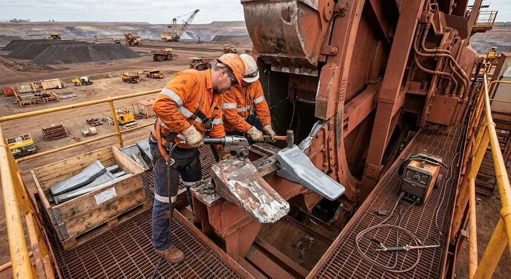
Create safe access to inspect and repair buckets, liners, chutes, conveyors, drives, brakes, luffing, slew, bogies, structure, power and control systems.
Engineering-led overhauls can include slew-bearing intervention, gearbox rebuilds, rail correction, structural repairs, control-system upgrades and obsolescence removal.
Planned outage logic
Exact sequencing, permits, isolation and test requirements belong to the operating site and authorised technical team.
Confirm the workfront, drawings, condition evidence, spares, temporary works, lifting studies, access, cleaning, isolations and inspection hold points.
Establish safe access, expose the component and record as-found wear, alignment, lubrication, fastener, electrical and structural condition before repair.
Complete the approved mechanical, structural, conveyor, electrical or control-system scope with traceable parts and authorised repair methods.
Record dimensions, bolt or tension data, NDT, alignment, lubrication, settings, protection tests and signed inspection or test-plan hold points.
Close guards and access, complete de-isolation controls, test functions and interlocks under the approved plan, then hand over defects and configuration changes.
Critical-risk boundary
Electrical energy, hydraulic pressure, suspended or balanced loads, gravity, brakes, counterweights, belt tension, moving stockpile material and adjacent operating equipment can all matter. Identify every energy source, isolate and control stored energy, and verify the isolation under the site's approved procedure. Never use this page as an isolation plan.
Open the model plant-risk code ↗People around the asset
Competency and authorisation are role-, task- and site-specific. A trade certificate alone does not authorise every task on the machine.
Position the machine and stockpile for the job, report abnormal behaviour, manage operating interfaces and support controlled testing.
Drives, gearboxes, bearings, couplings, lubrication, luffing, slew, bogies, brakes, chutes and mechanical alignment.
HV/LV isolation interfaces, motors, drives, cable systems, instruments, protection, PLC I/O and functional verification within authorisation.
Buckets, liners, chutes, frames, access steel and approved structural repairs supported by inspection and engineering requirements.
Engineered lifting, component handling and compliant access for heavy, awkward workfronts with constrained laydown and line-of-fire risks.
Boom and yard-conveyor belt inspections, repairs, change-outs, splices and return-to-service evidence.
Structural NDT, vibration, thermography, ultrasound, oil analysis, dimensional checks and clear feedback that closes the defect loop.
Scope, job plans, critical paths, parts, technical decisions, failure history, QA records, commissioning and maintenance strategy.
For resumes and interviews
Build, upgrade and life extension
Material properties, stockyard geometry, required rate, downstream capacity, structural loads, automation philosophy and maintainability define the machine.
Foundations, twin rails, yard conveyor, drainage, power, controls, water and communications must meet the machine and site tolerances.
Travel gear, portal, slew platform, pylon, working boom, counterweight, wheel and conveyors are assembled under engineered lift and temporary-work plans.
Drives, PLC, instruments, positioning, communications, safeguards and stockyard sequence logic are configured and verified.
No-load checks, controlled material trials, throughput and functional testing, documentation, training and defect close-out support operations acceptance.
Supplier and contractor map
These are capability categories, not a preferred-vendor list. Confirm site approval, technical authority, current capability and commercial terms.
Stockyard layout, machine selection, structural and mechanical design, controls, erection, commissioning, upgrades and technical authority.
Material-specific wear packages, bucket refurbishment, liner attachment, field measurement and traceable replacement components.
Bearing assessment or supply, gear contact, bolt preload measurement, jacking and change-out methods, lubrication and condition evidence.
Gearboxes, hydraulic or electric drives, motors, couplings, brakes, bearings, oil analysis, overhaul and test records.
Belting, splices, pulleys, idlers, cleaners, skirting, chutes, liners, dust controls and cable-management systems.
NDT, survey, scaffolding, rope access where approved, cranes, rigging, temporary works, machining, fabrication and shutdown execution.
Before asking for a quote
A generic request for “BWR buckets”, “a slew bearing” or “a gearbox overhaul” creates commercial and technical risk.
Machine tag, OEM, model or arrangement and the exact workfront
Current drawing, bill of material and part or asset number—not only a site nickname
Commodity, bulk density, moisture, lump size, abrasiveness and actual operating duty
Measured as-found condition, wear map, clear photographs and recent inspection or NDT evidence
Failure history, desired service life and the engineering or OEM acceptance criteria
Shutdown dates, access route, laydown, lifting capacity, working-at-height and isolation constraints
Materials, welding, coating, inspection-and-test plan, traceability and document requirements
Commissioning, testing, spare-parts, warranty, technical support and lead-time expectations
Published benchmark
20,000tonnes per hourTAKRAF and thyssenkrupp each publish bucket-wheel reclaimer product data reaching 20,000 t/h. Numbers at this scale explain the focus on availability, transfer interfaces, critical spares and disciplined outage execution—but they must never be applied to an unidentified machine.
Quick answers
A dedicated reclaimer removes material from a stockpile. A combined stacker-reclaimer uses one machine for both duties, normally with a reversible boom conveyor and a yard-conveyor interface designed for each operating mode. Combined machines add flexibility but cannot stack and reclaim simultaneously.
No. TAKRAF publishes a broad family range of 500 to 20,000 tonnes per hour. Actual capacity is machine- and material-specific and depends on bulk density, stockpile geometry, cut depth, bucket fill, conveyor limits and downstream availability.
Yes, machines can be manual, semi-automated, remote or fully automated depending on design. Reliable positioning, collision avoidance, communications, instruments, sequence logic and clear recovery procedures are essential parts of remote operation.
There is no universal single failure mode. High-consequence areas commonly include structure, slew system, luffing, wheel drive, long travel, brakes, conveyor interfaces and control or protection systems. Site history and condition data should set priorities.
Source desk
Source-checked 9 September 2026. Supplier case studies describe particular applications and should not be generalised to every machine.
Published product range, boom- and bridge-type design context and automation options.
When one machine is designed to perform both stacking and reclaiming duties.
A multi-material example covering variable-speed drives, chute buildup controls and anti-collision logic.
OEM technical data and context for dedicated reclaimers, combined stacker-reclaimers, automation and turnkey delivery.
Official operating context for the South Flank and Mining Area C iron ore hub.
OEM starting point for FAM stockyard-machine configurations and enquiries.
Supplier case study on slew-ring fastener condition and ultrasonic preload measurement.
Supplier case study on wear-plate selection and fabricated liners for reclaimer buckets.
Supplier case study on belt selection and service-life improvement on Pilbara stacker-reclaimer boom conveyors.
Model code covering plant risk management, guarding, maintenance and hazardous-energy isolation principles.
Scope boundary: This independent guide explains the asset and helps readers ask better questions. It is not an OEM manual, engineering instruction, maintenance tactic, inspection standard, work method, isolation plan or substitute for competent supervision and site-controlled procedures.