What enters?
Material size, condition, rate, energy and the upstream equipment handing it over.


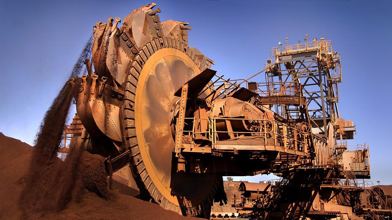
Australian mining equipment library
Four commodity systems and 27 connected equipment families across iron ore, coal, lithium and gold. Follow each machine's purpose, major systems, maintenance focus and material handover.
Choose a commodity
Compare the machines used in iron ore, coal, lithium and gold—from extraction and processing to the final product handover.
How to use the library
A crusher cannot deliver if its feeder starves or floods it. A reclaimer can be mechanically healthy and still stop because the outbound conveyor is unavailable. A shiploader depends on the stockyard, berth, vessel plan and upstream product supply. This iron ore guide treats equipment as one operating system; use the commodity selector above to open the coal, lithium and gold systems.
Start with purpose. Trace the material path. Then examine the assemblies, controls, condition and handover points.
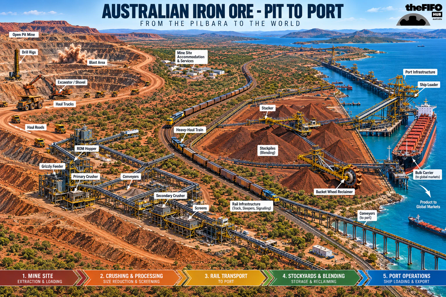
Iron ore system map
The pulse shows direction, not equipment speed or process timing. Real routes and bypasses vary by operation.
 Open full size ↗
A practical reading model
Material size, condition, rate, energy and the upstream equipment handing it over.
The machine may move, reduce, classify, store, reclaim, measure or position the material.
Structure, shafts, bearings, belts, wheels, rails, hydraulics and other load paths.
Power, drives, PLC logic, instruments, communications, safeguards and operator decisions.
The material stream, condition, rate, location and information handed to the next stage.
Iron ore equipment index
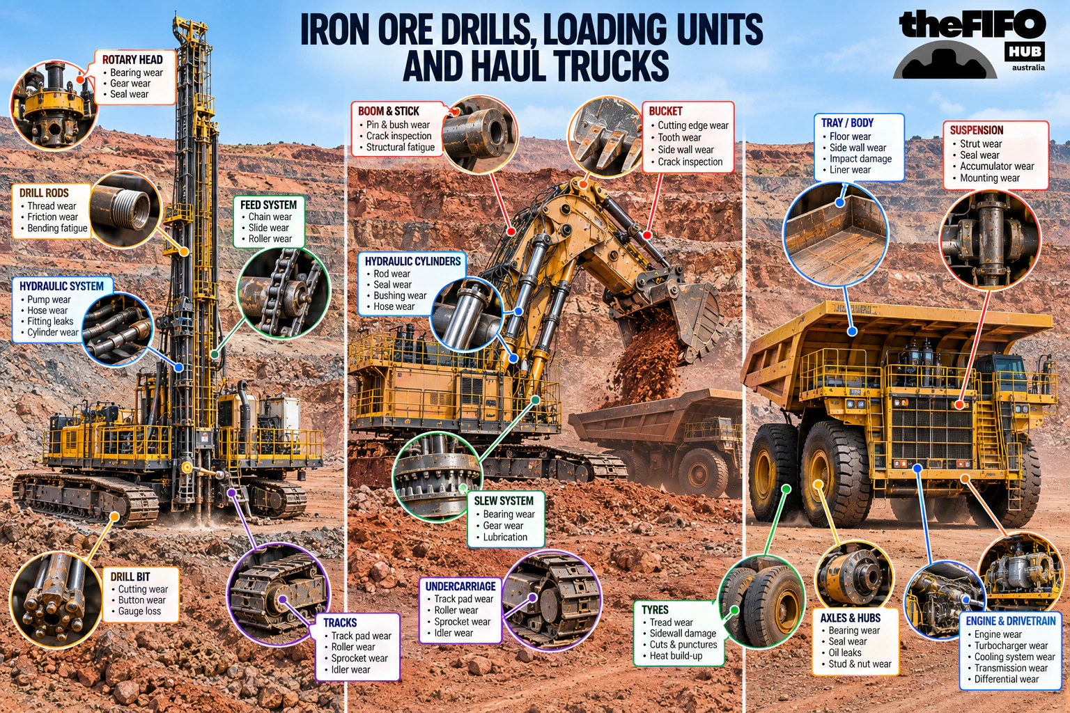
Fragment, excavate and move run-of-mine ore from the active mining area to the first fixed-plant handover.
 Open full size ↗
Operating principle
Production drills create a controlled pattern of blast holes. After blasting, excavators or shovels load fragmented material into haul trucks. The haulage system then links the face to the crusher, stockpile or waste destination. Payload, road condition, dispatch, queueing and equipment availability all affect the rate delivered to the plant.
Major assemblies
Mast, feed or pulldown, rotary head, drill string, air system, dust control and machine controls.
Boom, stick, bucket or dipper, swing system, crowd or hoist system, undercarriage and operator or automation controls.
Engine or electric drive, wheel motors or transmission, retarding and brakes, steering, suspension, tyres and dump body.
Dispatch, positioning, communications, haul roads, loading areas, dumps, fuel or charging and ancillary equipment.
Maintenance disciplines
Common degradation
People around the asset
Configuration boundary: Truck payload, drive system, loading-tool match and drill method vary widely. Treat OEM figures as machine-specific, not a generic Pilbara standard.
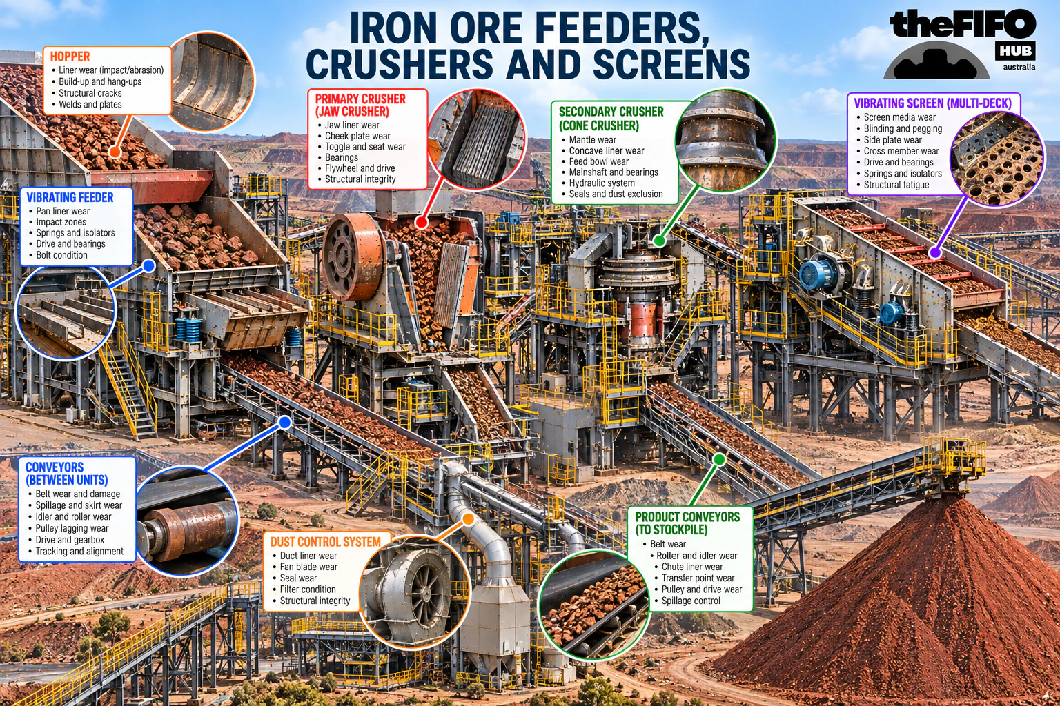
Control the feed, reduce rock size and separate material into the streams required by the process and product plan.
 Open full size ↗
Operating principle
A ROM bin receives trucked or conveyed ore. A heavy-duty feeder meters the load into the primary crusher instead of allowing an uncontrolled surge. The crusher reduces top size. Screens then classify the stream: material that meets the target can move forward, while oversize may return for further crushing. The exact arrangement depends on ore characteristics and product requirements.
Major assemblies
Dump pocket or bin, rock-breaker interface, protective structure, level detection and dust management.
Apron pans or belt, chains, rollers, sprockets, drive, tensioning and support frame that regulate the feed rate.
Gyratory, jaw, cone or other reduction chamber, main shaft or rotor, drive, lubrication, hydraulic and wear components.
Decks and media, exciters or drive, springs, support structure, chutes and separate discharge streams.
Maintenance disciplines
Common degradation
People around the asset
Configuration boundary: Primary, secondary and tertiary stages are site-specific. Crusher type, closed- or open-circuit screening and recirculating load depend on the ore and process design.
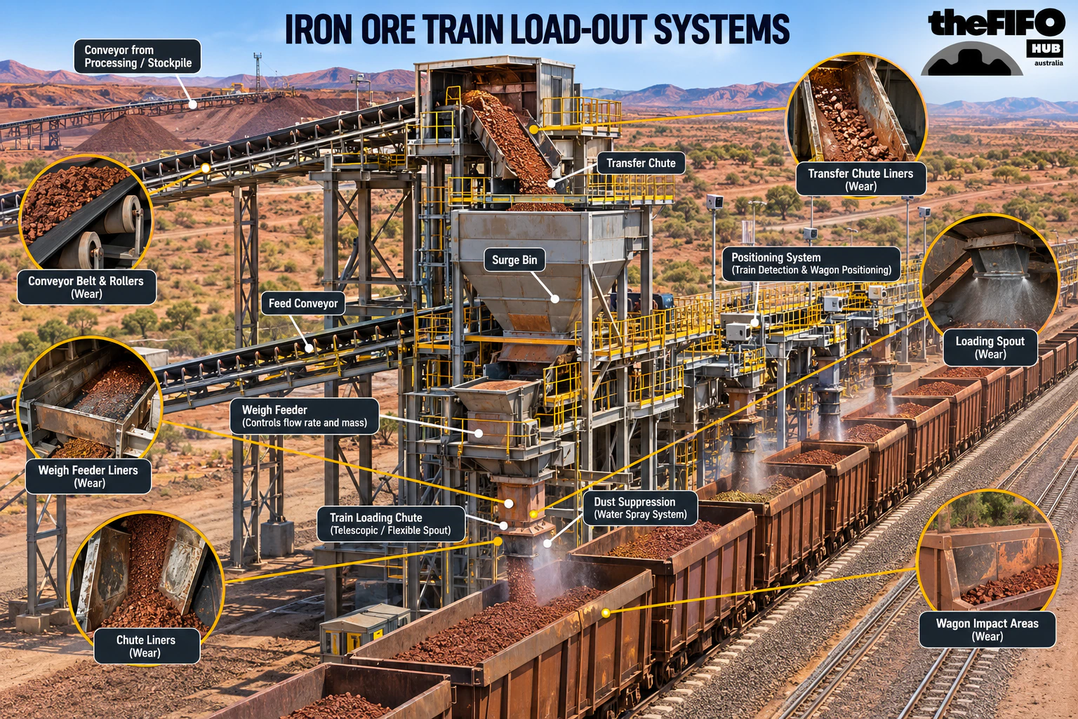
Transfer saleable ore into each wagon at a controlled rate and mass before the train leaves the mine.
 Open full size ↗
Operating principle
A surge or load-out bin decouples the upstream conveyor from individual wagon loading. Gates or feeders meter ore into each moving or indexed wagon. Weighing, level and train-position systems help control the load profile and avoid overloading or uneven distribution. Sampling and product tracking may operate alongside the loading sequence.
Major assemblies
Surge or load-out bin, structure, liners, level instruments and controlled discharge openings.
Gates, feeders, chutes and profile-control arrangements that place ore into the wagon.
Weighing, sampling, train detection, position and speed feedback linked to the loading logic.
PLC, field instruments, train communications, alarms, interlocks and production records.
Maintenance disciplines
Common degradation
People around the asset
Configuration boundary: Batch and continuous load-out arrangements differ. The acceptable wagon load and profile come from the railway, wagon, track and operating requirements—not a generic target.
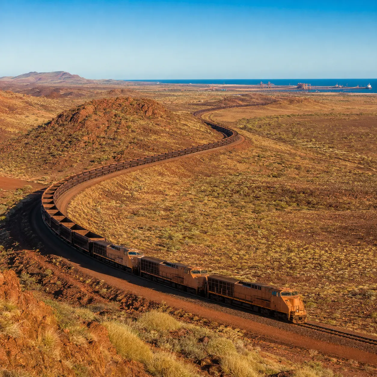
Move large quantities of iron ore from inland mining hubs to coastal stockyards and port terminals.
Operating principle
Diesel-electric locomotives—and increasingly battery-electric units in trials or mixed consists—convert energy into tractive effort. Distributed power and train-control systems coordinate locomotives along the consist. Ore cars carry the load while couplers, bearings, braking equipment, track, signalling and communications work as one railway system.
Major assemblies
Prime mover or battery system, alternator, traction equipment, cooling, braking, controls and communications.
Body, doors or rotary-dumper compatibility, bogies, wheelsets, bearings, couplers and brake equipment.
Rail, sleepers, ballast, formation, points, crossings, drainage and trackside monitoring.
Signalling, communications, distributed power, train protection, wayside detection and network control.
Maintenance disciplines
Common degradation
People around the asset
Configuration boundary: Train length, locomotive placement, braking system and axle load are network-specific. Public examples describe particular fleets, not a universal Pilbara configuration.
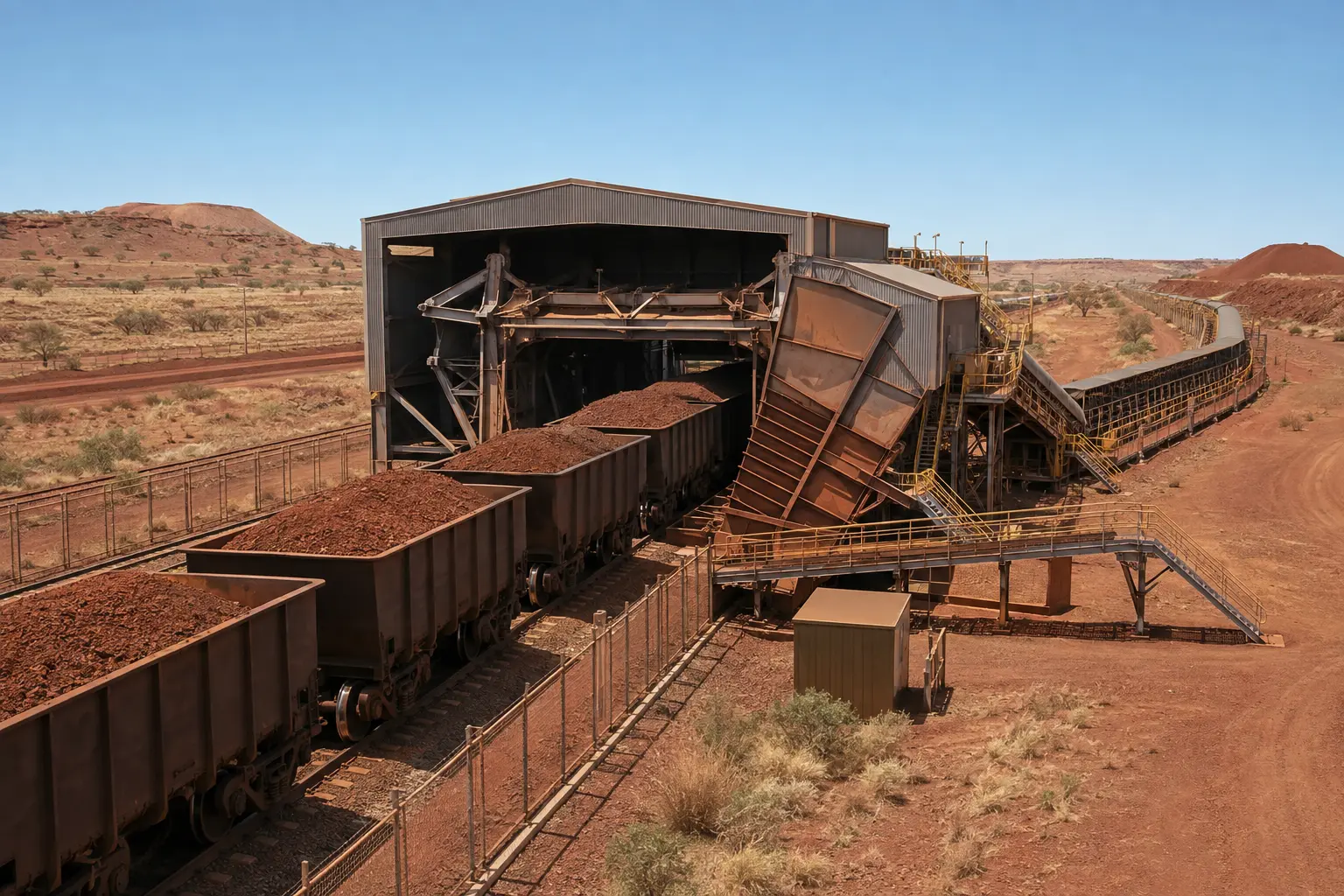
Index and empty ore cars into the port materials-handling stream while managing the train as a controlled sequence.
Operating principle
A positioner or indexer moves one or more wagons into the dumper. Clamps and support systems secure the cars in the designed position. The barrel rotates—or another unloading arrangement operates—so ore falls into a hopper below. Feeders then draw material out at a controlled rate for the downstream conveyor.
Major assemblies
Indexer or positioner arms, rail clamps, wheel grippers, drives and position feedback.
Barrel or tippler structure, clamps, support rollers, drive, braking and locking systems.
Hopper, grizzly where fitted, liners, feeders, dust control and discharge conveyor.
Train detection, permissives, interlocks, communications and synchronised machine logic.
Maintenance disciplines
Common degradation
People around the asset
Configuration boundary: Single, tandem, rotary and side-unloading systems exist. Wagon design and terminal sequence determine how a train can be unloaded.
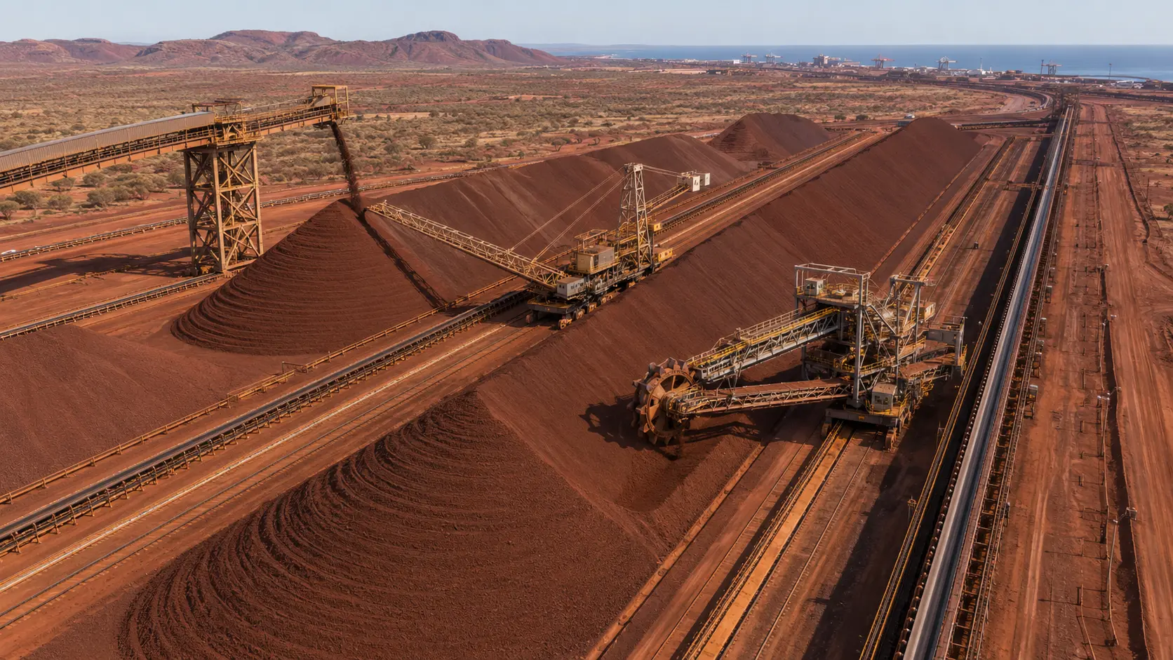
Place incoming product into controlled stockpiles so the operation can store, sequence and blend ore before shipment.
Operating principle
A yard conveyor carries ore beside the stockyard. A tripper transfers the stream onto the stacker’s boom conveyor. Long travel selects the position along the yard; slew and luff movements place ore across the pile. Stacking patterns influence segregation, blending, reclaim access and the stockyard’s ability to respond to the shipping plan.
Major assemblies
Incoming conveyor, tripper car, transfer chute, cable systems and machine interface.
Belt, pulleys, idlers, drive, take-up, discharge chute and boom structure.
Long travel bogies, rail clamps, slew bearing and drives, luff system, brakes and storm restraints.
Positioning, pile profile, collision avoidance, dust control, communications and sequence logic.
Maintenance disciplines
Common degradation
People around the asset
Configuration boundary: Chevron, windrow, cone-shell and other stacking patterns are process decisions. Stacker, combined stacker-reclaimer and fixed stacking arrangements differ by yard design.
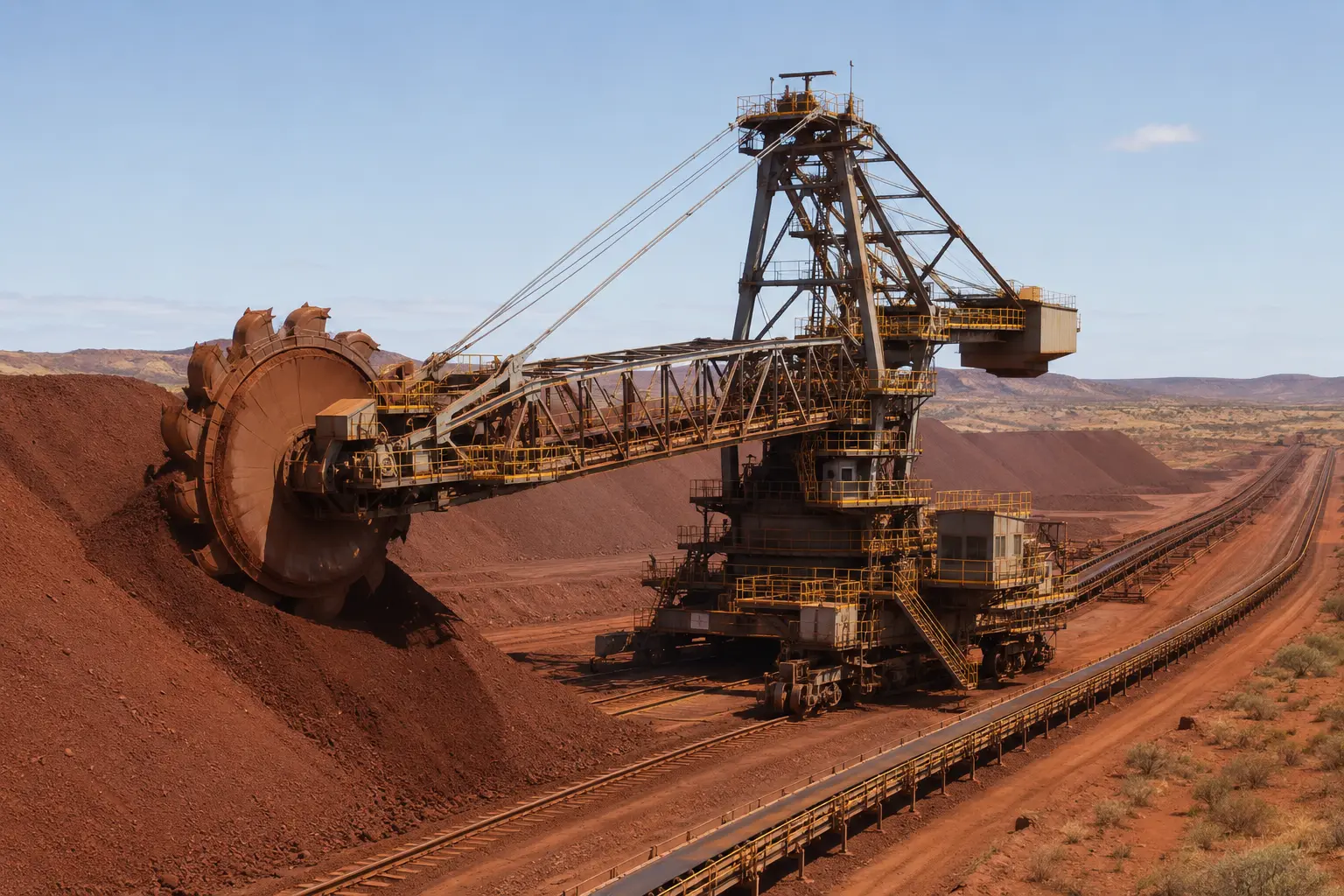
Recover nominated product from a stockpile at a controlled rate and place it onto the outbound conveyor system.
Operating principle
The bucket wheel cuts into the stockpile face. Buckets lift the ore and discharge it through a chute onto the boom conveyor. Slewing sweeps the wheel across the face, luffing adjusts boom elevation and long travel advances the machine along the stockpile. The reclaim method is coordinated with stockpile geometry, material condition and downstream demand.
Major assemblies
Wheel body, buckets and teeth, liners, hub, shaft, bearings, drive and discharge chute.
Belt, pulleys, idlers, drive, take-up, cleaners, skirts and boom support structure.
Slew bearing and drives, luff winch or cylinders, long-travel bogies, rails, brakes and clamps.
Power distribution, cable reel or festoon, PLC, instruments, communications, lubrication and dust control.
Maintenance disciplines
Common degradation
People around the asset
Configuration boundary: Wheel diameter, number of buckets, reclaim rate, boom length and machine motions are design-specific. Always use the current machine drawings and OEM data.
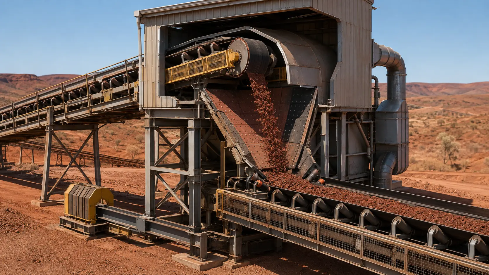
Move bulk material continuously between equipment and process stages, often over long distances and through multiple transfers.
Operating principle
A drive pulley transfers torque into the belt. Carry idlers support the loaded belt and return idlers support the empty side. The take-up maintains the designed tension regime. At a transfer point, the outgoing trajectory, chute geometry, liners, skirting and receiving belt work together to control loading, impact, wear, spillage and dust.
Major assemblies
Belt carcass and covers, splices, cleaners, skirting, tracking devices and condition monitoring.
Drive pulley, motor, gearbox or gearless drive, coupling, brakes, holdbacks and guarding.
Idlers, frames, stringers, pulleys, bearings, gravity or winch take-up and supporting structure.
Head chute, wear liners, impact zone, receiving belt, sealing, dust control and blocked-chute or belt-protection instruments.
Maintenance disciplines
Common degradation
People around the asset
Configuration boundary: Belt width, speed, tension, drive arrangement, idler spacing and transfer geometry are engineered for a particular duty. Generic numbers are unsafe substitutes for the approved design.
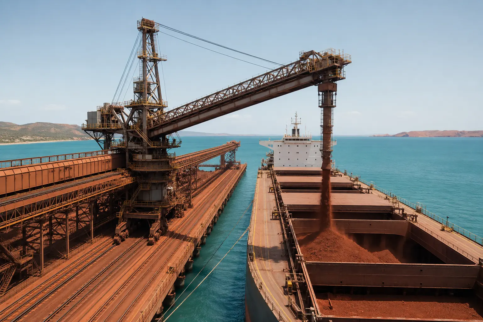
Transfer ore from the wharf conveyor into nominated vessel holds according to the terminal and vessel loading plan.
Operating principle
The wharf conveyor feeds the shiploader boom. Long travel positions the machine along the berth; luffing, slewing or shuttling places the discharge over the nominated hold. A telescopic chute or spoon controls the final drop. Loading is coordinated with the vessel plan, berth limits, marine conditions and upstream stockyard supply.
Major assemblies
Approach conveyor, tripper or transfer, machine feed chute, cable management and communications.
Belt, pulleys, idlers, drive, shuttle where fitted, supporting structure and discharge end.
Long travel, luff, slew or shuttle systems, brakes, rails, bogies, storm restraints and collision protection.
Telescopic sections, spoon or trimming arrangement, wear components, dust control and position feedback.
Maintenance disciplines
Common degradation
People around the asset
Configuration boundary: Travelling, radial, quadrant and other shiploader arrangements exist. Published Port Hedland loading rates are berth-specific and should not be generalised across terminals.
Maintenance matrix
The strongest maintenance decisions combine field observations, condition data, technical authority, work history and operating context.
Plain-language glossary
Authoritative starting points
Source-checked 30 August 2026. Confirm details against current OEM and site-controlled documents.
Official overview of the integrated Pilbara mines, processing hubs, rail and port system.
OEM overview of large mechanical- and electric-drive mining truck systems.
OEM range and configuration context for rotary and down-the-hole production drills.
OEM explanation of size reduction, classification and circuit interaction.
OEM overview of apron, belt and other feeding equipment used to control material flow.
OEM context for distributed power, locomotive technology and Pilbara iron ore rail applications.
OEM overview of rotary, crescent and side-unloading railcar-dumper systems and train positioners.
OEM library covering stackers, reclaimers, conveyors and shiploaders.
OEM material on conveyor belts, belt monitoring and specialist conveying configurations.
Current berth, wharf and published Port Hedland shiploader information.
Scope: This independent library explains equipment purpose, interfaces and maintenance disciplines. It is not a maintenance instruction, inspection standard, isolation plan or substitute for competency, supervision, engineering authority, OEM manuals, drawings and approved site procedures.