Material duty
What enters, what changes and what product or waste stream leaves.


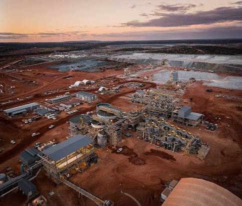
Australian mining equipment · Lithium
Follow the equipment used to mine Australian hard-rock lithium, reject waste, recover spodumene concentrate and prepare it for transport or downstream chemical conversion.
Choose a commodity
Compare the machines used in iron ore, coal, lithium and gold—from extraction and processing to the final product handover.
Why the equipment changes
Hard-rock lithium operations are concentrators, not miniature iron ore ports. Open-pit or underground fleets deliver pegmatite ore into crushing and sorting. Dense-medium separation, grinding and flotation can then recover spodumene, while thickeners and filters prepare concentrate and recover water. Some downstream facilities add kilns, leach reactors, purification and crystallisation—but those conversion systems may be hundreds or thousands of kilometres from the mine.
Start with the material. Follow what each machine changes, then read the handover to the next system.
Functional process graphic
This is a representative system map. Individual mines can use alternatives, bypass stages or locate downstream processing away from the mine.
Read the whole machine
The visible machine is only one part of the system. Utilities, controls, access, material condition and the next handover all influence whether it performs.
What enters, what changes and what product or waste stream leaves.
Structures, drives, wear parts, bearings, hydraulics, piping and load paths.
Power, instruments, PLC or DCS logic, communications, safeguards and interlocks.
Ore variability, quality targets, hazards, approved limits and the downstream constraint.
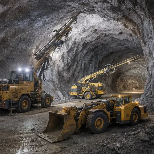
Recover lithium-bearing pegmatite selectively while controlling dilution, ore loss and the delivery of different material types.
Operating principle
Open-pit operations use production drills, blasting, excavators or shovels and haul trucks. Underground operations can use development jumbos, longhole production drills, charge-up equipment, underground loaders or boggers and trucks. Grade control, ore spotting and dispatch keep ore domains and waste separate because dilution can quickly reduce concentrator performance.
Major equipment and systems
Blast-hole drills, excavators or shovels, haul trucks, dozers, graders, water carts and dispatch.
Jumbos, bolters, ground-support equipment, service vehicles, ventilation and dewatering systems.
Longhole drills, charge-up units, loaders or LHDs, underground trucks, ore passes and crushing interfaces.
Grade-control drilling, sampling, survey, fleet positioning, stockpile identification and material-tracking systems.
Maintenance focus
Condition and process watch
People around the system
Configuration boundary: Mining method, stope design, fleet size and grade-control practice depend on the orebody and approved mine plan. Open-pit and underground equipment should not be treated as one interchangeable fleet.
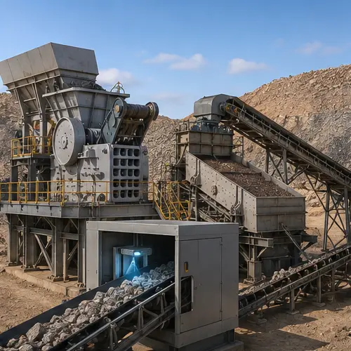
Reduce ore to a controlled size and reject barren or lower-value material before energy-intensive concentration.
Operating principle
Feeders regulate ore from the ROM bin into primary and secondary crushing. Screens classify the stream and return oversize where required. A sensor-based sorter presents individual particles to detection systems that identify selected mineral or waste characteristics; high-speed ejectors then direct particles into separate streams. Sorting can reduce the tonnes sent into grinding and wet processing when the orebody and testwork support it.
Major equipment and systems
ROM bin, apron or belt feeders, jaw or gyratory primary crusher, cone or other secondary crusher and chutes.
Vibrating screens, media, exciters, transfer conveyors and recirculating-load routes.
Feed preparation, presentation conveyor, sensors, illumination or detection systems, high-speed ejectors and separation chutes.
Belt scales, metal detection, dust control, blocked-chute protection, sampling and material tracking.
Maintenance focus
Condition and process watch
People around the system
Configuration boundary: Sensor type, particle-size window, detection threshold and ejection logic are orebody-specific. Sorting performance must be established through representative testwork and current operating data.
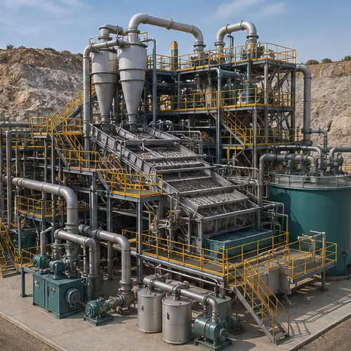
Separate spodumene-bearing particles from lower-density gangue before or instead of finer grinding for suitable size fractions.
Operating principle
A dense-medium circuit creates a suspension—commonly water with fine ferrosilicon—whose density sits between the valuable mineral and gangue. Feed enters a dense-medium cyclone or related separator. Centrifugal flow and density differences divide the particles into concentrate and reject streams. Drain-and-rinse screens recover medium, while magnetic separators and sumps return it to the circuit. Stable feed sizing and medium density are central to separation performance.
Major equipment and systems
Sizing and desliming screens, mixing box, correct-medium tank, density measurement and feed pump.
Dense-medium cyclone or classifier, distributor, wear liners, vortex finder, spigot and product launders.
Drain-and-rinse screens, dilute-medium sumps, magnetic separators, densifier and return-water circuit.
Density and pressure instruments, flow measurement, sampling, valves, PLC or DCS control and alarms.
Maintenance focus
Condition and process watch
People around the system
Configuration boundary: Not every spodumene ore is suited to the same DMS cut density, feed-size range or flowsheet. Mineralogy, liberation and testwork determine whether DMS is used and how it is configured.
Liberate spodumene from gangue and selectively recover it into a higher-grade concentrate stream.
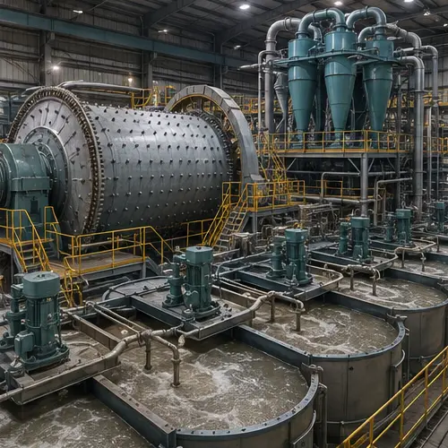
Operating principle
SAG, ball, vertical or other grinding mills reduce particle size. Mill-discharge pumps feed hydrocyclones, which send coarse material back to the mill and pass suitably fine slurry onward. Conditioning tanks add site-specific reagents and manage pulp chemistry. Flotation cells disperse air through agitated slurry; selected mineral particles attach to bubbles and report to froth, while rougher, scavenger and cleaner duties build recovery and grade.
Major equipment and systems
Mill shell, liners, grinding media, drive, lubrication, trommel or discharge screen and inching arrangements.
Mill-discharge sump and pumps, hydrocyclone cluster, feed distributor, valves and density measurement.
Conditioning tanks, flotation cells, mechanisms, air blowers, dart valves, froth launders and recirculation.
Reagent storage and dosing, pH or chemistry instruments, online analysers, samplers and plant DCS.
Maintenance focus
Condition and process watch
People around the system
Configuration boundary: Grinding energy, target size, flotation chemistry and circuit duties are determined by ore mineralogy and metallurgical testwork. Reagent details and setpoints are site-controlled.
Recover process water, reduce concentrate moisture, verify product quality and transfer spodumene concentrate into the logistics chain.
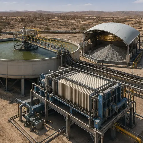
Operating principle
A thickener uses gravity settling and flocculation to increase slurry density while returning clarified overflow water to the plant. Pressure, vacuum or other filters remove additional water and form a concentrate cake. Conveyors or mobile equipment transfer the product into covered storage. Sampling, weighing and laboratory release support dispatch, while covered road combinations can move concentrate to port or a converter.
Major equipment and systems
Feedwell, rake mechanism, drive, bed-level and torque instruments, flocculant system, underflow pumps and overflow launders.
Pressure or vacuum filters, cloths or media, hydraulic or vacuum systems, wash water and cake discharge.
Concentrate conveyors, bins or sheds, front-end loaders, dust and moisture controls, weighbridge and sampling.
Tailings thickening or filtration, slurry pumps, return-water systems, pipelines and monitored storage interfaces.
Maintenance focus
Condition and process watch
People around the system
Configuration boundary: Filter type, target moisture, storage method, dangerous-goods classification, haulage controls and tailings arrangements depend on the product, climate, customer and approvals.
Transform spodumene concentrate into a refined lithium chemical suitable for qualified downstream customers.
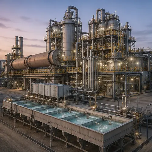
Operating principle
Conventional conversion can use thermal treatment in a rotary kiln or calciner to change spodumene crystal structure before roasting, leaching, purification and crystallisation. Alternative flowsheets can use different alkaline or hydrometallurgical routes. Reactors suspend solids and control temperature or chemistry; filters separate residues; precipitation, ion-exchange or other purification systems remove impurities; evaporators and crystallisers form the final lithium salt before drying and packaging.
Major equipment and systems
Rotary kiln or calciner, burner or electric heating, feed and discharge seals, drive, refractory, cooler and gas cleaning.
Atmospheric reactors or autoclaves, agitators, heating or cooling, reagent dosing, slurry pumps and ventilation.
Filters, clarifiers, precipitation tanks, ion exchange or route-specific impurity-removal equipment and analysers.
Evaporators, crystallisers, centrifuges or filters, dryers, packaging, quality laboratory and controlled storage.
Maintenance focus
Condition and process watch
People around the system
Configuration boundary: Chemical-conversion flowsheets differ substantially and are not present at every mine. Process chemistry, equipment materials, operating windows and product specifications come from the approved plant design and current procedures.
Sources and further reading
Source-checked 30 August 2026. Confirm details against current OEM and site-controlled documents.
Operator account of the large crushing and sensor-based ore-sorting facility at the Pilgangoora Operation.
Operator overview of the underground mine, concentrator and transport route from Kathleen Valley to Geraldton.
Equipment and process overview spanning crushing, sorting, grinding, flotation, thickening, filtration and conversion.
OEM flowsheet context for spodumene processing, leaching, purification and crystallisation equipment.
OEM explanation of concentrate and tailings filtration, automation and solid-liquid separation.
Primary source connecting Pilgangoora concentrate with downstream lithium-hydroxide conversion.
Technical boundary: Lithium mineralogy, mining method, sorting response, DMS cut density, grinding and flotation performance, reagents, water balance, product specifications, chemical conversion and tailings systems vary by orebody and plant. This guide is conceptual and does not replace testwork, approved procedures, OEM manuals, drawings, isolation plans or competent supervision.