Material duty
What enters, what changes and what product or waste stream leaves.


Australian mining equipment · Gold
Follow the equipment used to mine Australian gold, liberate fine particles, recover metal through gravity and carbon circuits, and pour doré for secure refining.
Choose a commodity
Compare the machines used in iron ore, coal, lithium and gold—from extraction and processing to the final product handover.
Why the equipment changes
Gold equipment is built around recovery, accounting and security rather than bulk export. Open-pit or underground fleets may move millions of tonnes, but the saleable output can leave as a small number of doré bars. Between those points sit energy-intensive mills, abrasive slurry systems, gravity concentrators, leach tanks, carbon circuits, elution and electrowinning equipment, a controlled gold room and a separate refinery chain.
Start with the material. Follow what each machine changes, then read the handover to the next system.
Functional process graphic
This is a representative system map. Individual mines can use alternatives, bypass stages or locate downstream processing away from the mine.
Read the whole machine
The visible machine is only one part of the system. Utilities, controls, access, material condition and the next handover all influence whether it performs.
What enters, what changes and what product or waste stream leaves.
Structures, drives, wear parts, bearings, hydraulics, piping and load paths.
Power, instruments, PLC or DCS logic, communications, safeguards and interlocks.
Ore variability, quality targets, hazards, approved limits and the downstream constraint.
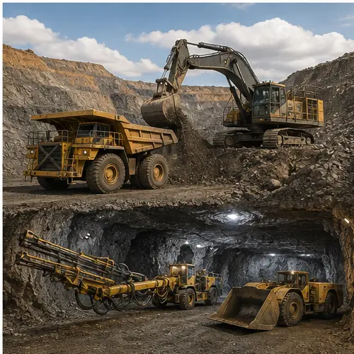
Recover planned ore selectively and deliver it to the processing route while separating waste and controlling grade.
Operating principle
Open pits use production drills, blasting, shovels or excavators and haul trucks. Underground mines use development jumbos, longhole production drills, ground-support equipment, loaders or boggers, trucks and sometimes shaft hoisting. Because gold grades can be measured in grams per tonne, grade control, ore spotting, stockpile discipline and reconciliation are as important as the physical fleet.
Major equipment and systems
Blast-hole drills, shovels or excavators, loaders, haul trucks, dozers, graders and dispatch.
Jumbos, bolters, scaling and shotcrete equipment, service vehicles, ventilation and dewatering.
Longhole drills, charge-up equipment, LHDs or boggers, trucks, ore passes, crushers and hoisting where fitted.
Grade-control drilling, sampling, survey, stockpile tracking, weigh systems and mine-to-mill reconciliation.
Maintenance focus
Condition and process watch
People around the system
Configuration boundary: Open-pit, sublevel caving, longhole open stoping and other methods create different equipment and risk profiles. Use the current mine design and statutory controls.
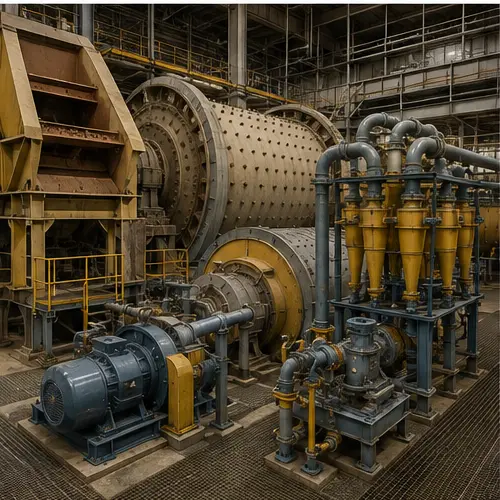
Reduce ore size and liberate gold-bearing minerals so downstream recovery equipment can access them.
Operating principle
ROM bins and feeders regulate ore into primary crushing. Secondary or tertiary crushers may reduce size further before milling. SAG or AG mills use ore and grinding media; ball or vertical mills provide additional size reduction. Mill-discharge pumps move abrasive slurry to hydrocyclones, which return coarse material to the mill and send fine overflow toward gravity or leach recovery. The circulating load ties the mill, pumps and cyclones together as one system.
Major equipment and systems
ROM bin, apron feeder, jaw or gyratory crusher, cone crushers where fitted, screens, conveyors and chutes.
Mill shell, liners, lifters, grinding media, drive, bearings, lubrication, feed and discharge systems.
Mill-discharge sump and pumps, hydrocyclone cluster, distributor, valves and density or pressure instruments.
Feed-rate control, power and load monitoring, particle-size measurement, samplers, PLC or DCS and protection systems.
Maintenance focus
Condition and process watch
People around the system
Configuration boundary: Crusher stages, mill type, target particle size and circulating load are ore- and plant-specific. Published equipment capacities or grind targets should not be transferred between sites.
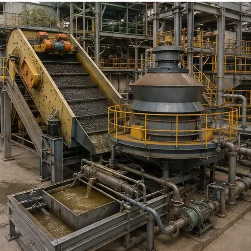
Capture liberated high-density gold early and reduce the amount circulating through the main recovery circuit.
Operating principle
A screen removes oversize before feed enters a centrifugal concentrator or another gravity device. High rotational forces and a fluidised concentrating surface retain dense particles while lighter gangue exits. The small concentrate stream can pass to an intensive leach reactor or directly into controlled gold-room treatment depending on the flowsheet. Gravity tails return to grinding or the main leach route.
Major equipment and systems
Cyclone underflow split, scalping screen, distributor, slurry valves and feed-water control.
Centrifugal bowl or cone, drive, fluidisation-water system, concentrate valves and discharge sequence.
Intensive leach reactor or secure concentrate transfer, reagent systems, filtration and solution tanks.
Controlled access, sampling, weighing, cameras, batch records and reconciliation interfaces.
Maintenance focus
Condition and process watch
People around the system
Configuration boundary: Gravity recoverable gold varies with mineralogy and grind. Concentrator duty, cycle timing and concentrate treatment are established through site testwork and controlled procedures.
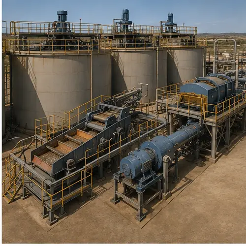
Dissolve recoverable gold into solution and load it onto activated carbon for downstream stripping.
Operating principle
In carbon-in-leach (CIL), cyanide leaching and adsorption onto activated carbon occur through the same agitated tank train. In carbon-in-pulp (CIP), leaching and adsorption stages are separated. Agitators keep solids suspended and distribute reagents and oxygen. Interstage screens retain carbon while slurry moves forward; carbon-transfer pumps or airlifts move carbon counter-currently. Safety, chemistry, water, detoxification and tailings systems are inseparable from the recovery equipment.
Major equipment and systems
Agitated tanks, shafts, gearboxes, impellers, baffles, oxygen or air systems, access and structural support.
Cyanide, lime and other route-specific storage, dilution, dosing, bunding, ventilation and instruments.
Activated-carbon inventory, interstage screens, carbon pumps or airlifts, safety screens and loaded-carbon transfer.
Detoxification where fitted, thickeners, slurry pumps, pipelines, return-water systems and monitored storage.
Maintenance focus
Condition and process watch
People around the system
Configuration boundary: Cyanide systems are hazardous and tightly controlled. Leach chemistry, detoxification, carbon movement, exposure controls and emergency response must follow the approved site design and procedures.
Strip gold from loaded carbon, recover it from solution and reactivate carbon for reuse.
Operating principle
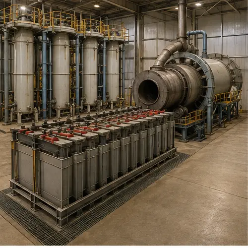
Loaded carbon is screened and washed, then treated through a controlled elution sequence that transfers gold into a concentrated solution. Electrowinning cells pass electric current through that solution so gold deposits onto cathodes or collection media. Filters recover the resulting sludge. A regeneration kiln heats stripped carbon under controlled conditions to restore adsorption activity before it returns to the CIL or CIP circuit.
Major equipment and systems
Loaded-carbon screen, acid-wash vessel where fitted, dewatering screens, transfer tanks and pumps.
Pressure-rated columns, solution tanks, heaters, heat exchangers, pumps, valves and automated sequence control.
Cells, cathodes, rectifier or DC power supply, solution circulation, ventilation and sludge recovery.
Dewatering, feed system, regeneration kiln, quench tank, screens, off-gas system and carbon return.
Maintenance focus
Condition and process watch
People around the system
Configuration boundary: Elution routes, temperatures, pressures, reagents, electrowinning design and regeneration conditions vary. These systems require authorised access and site-specific process-safety controls.
Dry and smelt recovered metal, pour accountable doré, secure it for transport and refine it to the required purity.
Operating principle
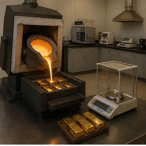
Recovered material is filtered, dried or calcined and mixed with route-specific fluxes before smelting in a furnace. Molten metal is poured into moulds to form doré bars. Cooling, cleaning, weighing, sampling, assay and reconciliation establish the accountable product. Secure transport moves doré to a refinery, where melting, sampling, chemical or electrolytic separation, casting and laboratory verification produce high-purity gold and recover silver or other payable metals.
Major equipment and systems
Sludge filters, drying or calcining ovens, enclosed handling, flux preparation and controlled workstations.
Furnace, crucibles, tongs and lifting aids, moulds, ventilation, fume extraction and refractory systems.
Calibrated scales, sampling tools, assay laboratory, cameras, access control, vault and dispatch records.
Receiving and melting furnaces, sampling, chemical or electrolytic refining, casting, analytical laboratory and secure storage.
Maintenance focus
Condition and process watch
People around the system
Configuration boundary: Gold rooms and refineries have restricted access, hazardous materials and high-value accounting controls. Smelting, assay, transport and refining must follow approved procedures and legal requirements.
Sources and further reading
Source-checked 30 August 2026. Confirm details against current OEM and site-controlled documents.
Operator description of underground mining and the crushing, grinding, gravity and carbon-in-leach route at the Granites plant.
Operator overview of the Super Pit, underground mines and the Fimiston and Gidji processing plants.
OEM case study tracing crushing, ball milling, cyclones, gravity recovery, CIL, elution, electrowinning and smelting.
OEM equipment overview covering acid wash, elution, electrowinning, drying, smelting and carbon regeneration.
Government-owned refiner overview of receiving, sampling, refining and producing high-purity precious metal.
Refinery information on gold and silver assaying and analytical laboratory services.
Technical boundary: Gold mining and processing can involve explosives, confined or underground work, high-energy comminution, abrasive slurry, cyanide, high temperature, pressure, high current, molten metal and high-value security systems. This guide is conceptual and does not replace competency, authorised access, approved procedures, OEM manuals, engineering drawings, isolation plans, chemical controls or emergency requirements.